0%

【光栅化渲染器】(四)纹理

上一节中我们完成了三维物体的渲染,显示了一个立方体,这一节我们为立方体加上一个图片纹理变为一个木箱。

1 OpenGL 中的纹理

首先来看 OpenGL 中如何使用纹理有关的操作,可以参考官方教程:[纹理 - LearnOpenGL CN](https://learnopengl-cn.github.io/01 Getting started/06 Textures/)

2 实现纹理类

然后我们自己手动实现一个简单的纹理类,纹理环绕方式使用 GL_REPEAT 的方式,即超过 1.0 的纹理坐标就直接重复,纹理过滤的方式采用最近邻方式,加载图片还是使用简单强大的 stbi 库,纹理类的实现如下:

1
2
3
4
5
6
7
8
9
10
11
12
13
14
15
16
17
18
19
20
21
22
23
24
25
26
27
28
29
30
31
32
33
34
35
36
37
38
39
40
41
42
43
44
45
46
47
48
49
50
51
52
53
54
55
56
57
58
59
60
61
62
63
64
65
66
67
68
69
70
71
72
73
74
75
76
77
78
79
80
81
82
83
84
85
86
87
88
89
90
91
92
93
94
95
96
97
98
99
100
101
102
103
104
105
106
107
108
109
/*
* 图片纹理类
*/

#pragma once

#ifndef TEXTURE_H
#define TEXTURE_H

#include "Global.h"

class Texture {

public:
int width;
int height;
int channels;
unsigned char* data;

Texture() : width(-1), height(-1), channels(-1), data(nullptr)
{}

Texture(const std::string& Path) {
LoadTexture(Path);
}

virtual ~Texture() {
if (data)
free(data);
}

Texture(const Texture& t) {
width = t.width;
height = t.height;
channels = t.channels;
if (t.data) {
data = (unsigned char*)malloc(width * height * channels);
memcpy(data, t.data, width * height * channels);
}
}

Texture& operator=(const Texture& t) {
width = t.width;
height = t.height;
channels = t.channels;
if (t.data) {
data = (unsigned char*)malloc(width * height * channels);
memcpy(data, t.data, width * height * channels);
}
return *this;
}

// 加载图片
virtual void LoadTexture(const std::string& Path) {
stbi_set_flip_vertically_on_load(false);
if (data)
free(data);
data = stbi_load(Path.c_str(), &width, &height, &channels, 0);
}

// 纹理采样,使用重复寻址方式,等同于OpenGL的GL_REPEAT
virtual glm::vec4 Sample2D(const glm::vec2& texcoord) {
float x = texcoord.x - (float)floor(texcoord.x);
float y = texcoord.y - (float)floor(texcoord.y);
x = x < 0 ? -x : x;
y = y < 0 ? -y : y;
return GetColor(x * (width - 1), y * (height - 1)) / 255.0f;
}

// 获取颜色,对不同通道纹理图片分别处理,以便于加载法线、高度纹理等
glm::vec4 GetColor(int x, int y) {
if (x < 0 || x >= width || y < 0 || y >= height)
return glm::vec4(0, 0, 0, 255);
switch (channels) {
case 1:
return GetColor1(x, y);
break;
case 2:
return GetColor2(x, y);
break;
case 3:
return GetColor3(x, y);
break;
case 4:
return GetColor4(x, y);
break;
default:
return glm::vec4(0, 0, 0, 255);
}
}
glm::vec4 GetColor1(int x, int y) {
int xy = y * width + x;
return glm::vec4(*(data + xy), 0, 0, 255);
}
glm::vec4 GetColor2(int x, int y) {
int xy = 2 * (y * width + x);
return glm::vec4(*(data + xy), *(data + xy + 1), 0, 255);
}
glm::vec4 GetColor3(int x, int y) {
int xy = 3 * (y * width + x);
return glm::vec4(*(data + xy), *(data + xy + 1), *(data + xy + 2), 255);
}
glm::vec4 GetColor4(int x, int y) {
int xy = 4 * (y * width + x);
return glm::vec4(*(data + xy), *(data + xy + 1), *(data + xy + 2), *(data + xy + 3));
}
};

#endif

然后修改 Shader 类,加入纹理成员,并修改片元着色器,将颜色改为纹理采样:

1
2
3
4
5
6
7
8
9
10
11
12
13
14
15
16
17
18
19
20
21
22
23
24
25
26
27
28
29
30
31
32
33
34
35
36
37
38
39
40
41
42
43
44
45
46
47
48
49
50
51
52
53
54
55
56
57
58
59
60
61
62
63
64
65
66
67
68
69
70
/*
* 着色器 Shader 类
*/
#pragma once
#ifndef SHADER_H
#define SHADER_H

#include "V2F.h"
#include "Vertex.h"
#include "Texture.h"

class Shader {
public:
Shader()
{
ModelMatrix = glm::mat4(1.0f);
ViewMatrix = glm::mat4(1.0f);
ProjectMatrix = glm::mat4(1.0f);
texture = new Texture();
};

virtual ~Shader() = default;

private:
glm::mat4 ModelMatrix;
glm::mat4 ViewMatrix;
glm::mat4 ProjectMatrix;
Texture* texture;


public:
// 顶点着色器
virtual V2F VertexShader(const Vertex& a2v) {
V2F o;
// 变换到世界空间
o.worldPos = ModelMatrix * a2v.position;
// 变换到裁剪空间
o.windowPos = ProjectMatrix * ViewMatrix * o.worldPos;
// 法线变换
o.normal = glm::normalize(NormalMatrix * a2v.normal);
o.texcoord = a2v.texcoord;
o.color = a2v.color;
return o;
}
// 片元着色器
virtual glm::vec4 FragmentShader(const V2F& v) {
if (texture->data)
{
glm::vec4 color = texture->Sample2D(v.texcoord);
return color;
}
return v.color;
}

void setModelMatrix(const glm::mat4& model) {
ModelMatrix = model;
}
void setViewMatrix(const glm::mat4& view) {
ViewMatrix = view;
}
void setProjectMatrix(const glm::mat4& project) {
ProjectMatrix = project;
}
void setTexture(std::string path)
{
texture->LoadTexture(path);
}
};

#endif

然后在 Draw 类中加入纹理图片路径:

1
2
3
4
5
6
7
8
9
10
11
12
13
14
15
16
17
18
19
20
21
22
23
24
25
26
27
28
29
30
31
32
33
class Draw {
private:
int Width;
int Height;
FrameBuffer* FrontBuffer;
Shader* shader;
glm::mat4 ViewPortMatrix;
std::string TexturePath;

public:

...

Draw(const int& w, const int& h, const std::string tpath) :
Width(w), Height(h), FrontBuffer(nullptr), shader(nullptr), TexturePath(tpath) {}

...

// 初始化,设定帧缓冲区和 Shder
void Init() {
if (FrontBuffer)
delete FrontBuffer;
if (shader)
delete shader;
ViewPortMatrix = GetViewPortMatrix(0, 0, Width, Height);
FrontBuffer = new FrameBuffer(Width, Height);
shader = new Shader();
shader->setTexture(TexturePath);
}

...

};

然后修改主函数:

1
2
3
4
5
6
7
8
9
10
11
12
13
14
15
16
17
18
19
20
21
22
23
24
25
26
27
28
29
30
31
32
33
34
35
36
37
#include "Global.h"
#include "Draw.h"

unsigned int SCR_WIDTH = 800;
const unsigned int SCR_HEIGHT = 600;
const std::string TEXTURE_PATH = "D:\\TechStack\\ComputerGraphics\\RenderEngine\\Assets\\Textures\\box.png";
const std::string OUT_PATH = "D:\\TechStack\\ComputerGraphics\\RenderEngine\\Results\\";
const std::string FILE_NAME = "texture_box2.png";

int main()
{
Draw dw(SCR_WIDTH, SCR_HEIGHT, TEXTURE_PATH);
// 初始化渲染器
dw.Init();
dw.ClearBuffer(glm::vec4(0, 0, 0, 1));

// 设置观察矩阵
dw.setViewMatrix(
GetViewMatrix(glm::vec3(0, 0, 5), glm::vec3(0, 0, -1), glm::vec3(1, 0, 0), glm::vec3(0, 1, 0)));
// 设置投影矩阵
dw.setProjectMatrix(
GetPerspectiveMatrix(glm::radians(60.0f), (float)SCR_WIDTH / SCR_HEIGHT, 0.3f, 100));

// 创建一个立方体
Mesh Box = CreateBox(glm::vec3(0.0, 0.0, 0.0), 0.5);
// 让模型在原点绕着(0,1,0)旋转angle度
float angle = 45.0;
dw.setModelMatrix(glm::rotate(glm::mat4(1.0f), glm::radians(angle), glm::vec3(0.0, 1.0, 0.0)));
// 绘制
dw.DrawMesh(Box);

// 写出图片
std::string filepath = OUT_PATH + FILE_NAME;
dw.show(filepath);

return 0;
}

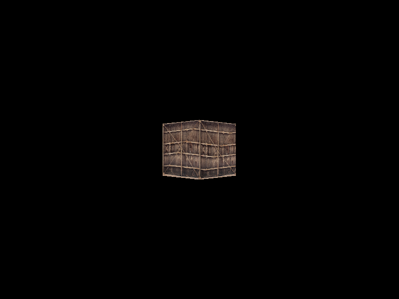
得到的效果:

texture_box

3 透视纹理映射

可以看出当立方体的面不正对我们的时候,纹理出现了变形。这是因为我们对顶点插值时使用的插值参数是通过顶点间的 x, y 坐标求出的,但是透视投影之后纹理坐标并不跟投影点 x , y 坐标线性相关。这种直接插值纹理坐标的方式被称为仿射映射,解决办法是做透视映射,具体可以查看深入探索透视纹理映射这篇文章。

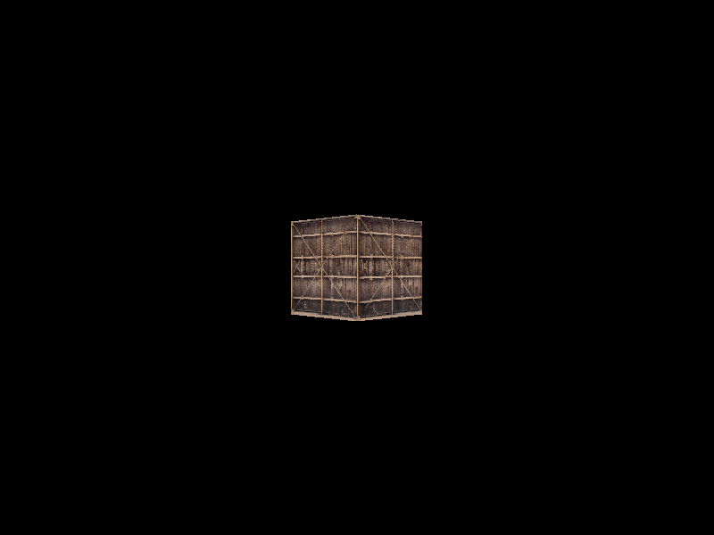
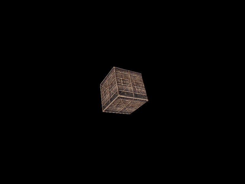
总之实际的做法就是在透视除法时,将除了屏幕坐标之外的所有值都除以 w 值,然后再进行插值,这样就可以得到正确的纹理映射关系,最后在扫描线函数中,调用片元着色器之前再乘以 w 恢复即可:

1
2
3
4
5
6
7
8
9
10
11
12
13
14
15
16
17
18
19
20
21
22
23
24
25
26
27
28
29
30
31
32
33
34
35
36
37
38
//透视除法
void PerspectiveDivision(V2F& v) {
// 记录下原本的 w
v.w = v.windowPos.w;
v.windowPos /= v.windowPos.w;
v.windowPos.w = 1.0f;
// OpenGL 的 NDC 中 Z 的范围是[0,1]
v.windowPos.z = (v.windowPos.z + 1.0) * 0.5;

//其他属性也要除以 w,以便于正确插值,之后在片元着色器之前再乘以原本的 w 恢复
v.worldPos /= v.w;
v.normal /= v.w;
v.texcoord /= v.w;
v.color /= v.w;
}

...

void ScanLine(const V2F& left, const V2F& right) {
int length = right.windowPos.x - left.windowPos.x;
for (int i = 0; i < length; ++i) {
V2F v = V2F::lerp(left, right, (float)i / length);
v.windowPos.x = left.windowPos.x + i;
v.windowPos.y = left.windowPos.y;

//深度测试
float depth = FrontBuffer->GetDepth(v.windowPos.x, v.windowPos.y);
if (v.windowPos.z <= depth) {
v.worldPos *= v.w;
v.normal *= v.w;
v.texcoord *= v.w;
v.color *= v.w;

FrontBuffer->WritePoint(v.windowPos.x, v.windowPos.y, shader->FragmentShader(v));
FrontBuffer->WriteDepth(v.windowPos.x, v.windowPos.y, v.windowPos.z);
}
}
}

得到的效果:

texture_box2

texture_box3

---- 本文结束 知识又增加了亿点点!----

文章版权声明 1、博客名称:LycTechStack
2、博客网址:https://lz328.github.io/LycTechStack.github.io/
3、本博客的文章部分内容可能来源于网络,仅供大家学习与参考,如有侵权,请联系博主进行删除处理。
4、本博客所有文章版权归博主所有,如需转载请标明出处。