0%

【光栅化渲染器】(三)变换与深度测试

上一节我们搭建了整个渲染器的框架,并实现了最简单的渲染二维图形。这一节我们开始渲染真正的三维物体,实现一个基本的渲染管线。

1 Mesh 类

网格(Mesh)是用于保存三维模型的数据结构,通常来说一个网格包含一系列顶点数据和索引,用它们就能绘制出一系列多边形。同时网格还包含该模型所使用的材质信息(贴图、光照等)。上一章中我们是直接用顶点来画图形的,相当于手动创建了一个 Mesh,但是当模型比较复杂的时候,就需要一个类来管理模型的 Mesh,于是我们创建一个 Mesh 类:

1
2
3
4
5
6
7
8
9
10
11
12
13
14
15
16
17
18
19
20
21
22
23
24
25
26
27
28
29
30
31
32
33
34
35
36
37
38
39
40
41
42
43
44
45
46
47
48
49
50
51
52
53
54
55
56
57
58
59
60
61
62
/*
* 网格类,基础单位是三角形
*/
#pragma once

#ifndef MESH_H
#define MESH_H

#include "Vertex.h"

class Mesh
{
public:
std::vector<Vertex> VBO; // 存放顶点数据
std::vector<unsigned int> EBO; // 存放顶点索引顺序

Mesh() = default;
Mesh(const int& vNum, const int& iNum) {
VBO.resize(vNum);
EBO.resize(iNum);
}
~Mesh() = default;

Mesh(const Mesh& mesh)
:VBO(mesh.VBO), EBO(mesh.EBO) {}

Mesh& operator=(const Mesh& mesh)
{
if (&mesh == this)
return *this;
VBO = mesh.VBO;
EBO = mesh.EBO;
return *this;
}

Mesh& operator+=(const Mesh& mesh)
{
AddMesh(mesh);
return *this;
}
// 向网格中加入其它网格
void AddMesh(const Mesh& mesh) {
int offset = VBO.size();
VBO.insert(VBO.end(), mesh.VBO.begin(), mesh.VBO.end());
EBO.reserve(EBO.size() + mesh.EBO.size());
for (int i = 0; i < mesh.EBO.size(); i++) {
EBO.push_back(mesh.EBO[i] + offset);
}
}

// 向网格中添加一一个三角形片面
void AddTriangle(const Vertex& v1, const Vertex& v2, const Vertex& v3) {
VBO.push_back(v1);
VBO.push_back(v2);
VBO.push_back(v3);
EBO.push_back(0);
EBO.push_back(1);
EBO.push_back(2);
}
};

#endif

然后我们就可以在 Draw 类中将之前画三角形的函数 DrawTriangle 改为更一般的画网格的函数 DrawMesh 了:

1
2
3
4
5
6
7
8
9
10
11
12
13
14
15
16
17
18
19
20
21
22
// 画网格
void DrawMesh(const Mesh& mesh) {
if (mesh.EBO.empty()) {
return;
}
for (int i = 0; i < mesh.EBO.size(); i += 3) {
Vertex p1, p2, p3;
p1 = mesh.VBO[mesh.EBO[i]];
p2 = mesh.VBO[mesh.EBO[i + 1]];
p3 = mesh.VBO[mesh.EBO[i + 2]];
// 顶点着色器
V2F v1, v2, v3;
v1 = shader->VertexShader(p1);
v2 = shader->VertexShader(p2);
v3 = shader->VertexShader(p3);
// 视口变换
v1.windowPos = ViewPortMatrix * v1.windowPos;
v2.windowPos = ViewPortMatrix * v2.windowPos;
v3.windowPos = ViewPortMatrix * v3.windowPos;
ScanLineTriangle(v1, v2, v3);
}
}

2 三维变换

接下来是重头戏,三维变换。虽然对三维坐标变换已经有过深入的理论学习,但是在实践之前还是有必要再复习一次,把理论和实际结合起来。之前的笔记参考【计算机图形学】(一)变换

首先梳理一下整个从三维模型到屏幕上的图像变换过程:

  • 模型定点定义在模型空间,需要将所有模型的顶点转换到世界空间
  • 世界空间中有各种模型和观察整个场景的相机,因此要将世界空间变换到相机空间,也称观察空间
  • 观察空间中的顶点位置还是三维坐标,因此要进行投影变换将所有物体顶点变换到裁剪空间,得到二维位置以及深度
  • 裁剪空间经过透视除法变换到标准设备坐标系
  • 标准设备坐标系最后经过视口变换到屏幕空间中

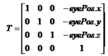
于是首先是世界空间到观察空间的变换,也就是将世界空间原点移动到相机位置,然后将世界空间的三个坐标轴和相机的 right、up、front 三个方向对齐。平移矩阵很好写出:

image-20220521165556253

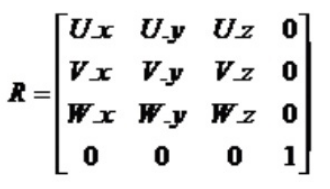
坐标轴对齐也很简单,要将 A 空间的坐标轴和 B 空间的坐标轴对齐,只需要将 A 空间下 B 空间的坐标轴按行排列即可,因此只要将世界坐标系下的相机的三个方向按行排列,就是从世界空间到相机空间的变换矩阵:

image-20220521165545686

于是整个视角变换矩阵即为:

image-20220521165714434

我们在 math.h 中加入视角变换矩阵:

1
2
3
4
5
6
7
8
9
10
11
12
13
14
15
16
17
18
19
20
21
22
23
24
25
26
27
28
// 视角变换矩阵,也称观察矩阵
// V = R*T
// T = [ 1 , 0 , 0 , -eyex R = [ Right , 0
// 0 , 1 , 0 , -eyey UP , 0
// 0 , 0 , 1 , -eyez - Front , 0
// 0 , 0 , 0 , 1 ] 0 , 1 ]
//V = [ Right , - Right·eye
// UP , - UP·eye
// -Front , Front·eye
// 0 , 1 ]
// OpenGL中观察空间是右手系,+z 轴指向屏幕外,为了让朝向保持不变,对Front向量取反

glm::mat4 GetViewMatrix(glm::vec3 pos, glm::vec3 front, glm::vec3 right, glm::vec3 up) {
glm::mat4 result = glm::mat4(1.0f);
result[0][0] = right.x;
result[1][0] = right.y;
result[2][0] = right.z;
result[3][0] = -glm::dot(right, pos);
result[0][1] = up.x;
result[1][1] = up.y;
result[2][1] = up.z;
result[3][1] = -glm::dot(up, pos);
result[0][2] = -front.x;
result[1][2] = -front.y;
result[2][2] = -front.z;
result[3][2] = glm::dot(front, pos);
return result;
}

接下来是透视投影矩阵,之前的笔记有详细推导,这里就不再赘述了,顺便再附上两篇透视投影的详细推导和理解的文章:

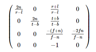
这里我们使用的透视投影矩阵为:

image-20220521172401734

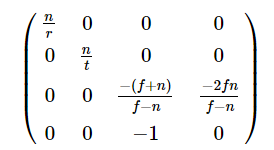
其中 r = -l, t = -b,因此投影矩阵最终为:

image-20220521172445502

其中,r 是屏幕半宽,t 是屏幕半高,f 是远平面距离,n 是近平面距离。代码如下:

1
2
3
4
5
6
7
8
9
10
11
12
13
14
15
16
17
18
//透视投影 参数 fov(弧度) aspect near far
//M = [ 1/aspect*tan(fov/2), 0 , 0 , 0
// 0 , 1/tan(fov/2) , 0 , 0
// 0 , 0 , - (f+n)/(f-n) , -2fn/(f-n)
// 0 , 0 , -1 , 0 ]
// 投影之后从右手系变成了左手系,+Z指向屏幕内
glm::mat4 GetPerspectiveMatrix(const float& fovy, const float& aspect, const float& n, const float& f)
{
glm::mat4 result = glm::mat4(0.0f);
const float tanHalfFov = tan(fovy * 0.5f);
result[0][0] = 1.0f / (aspect * tanHalfFov);
result[1][1] = 1.0f / (tanHalfFov);
result[2][2] = -(f + n) / (f - n);
result[2][3] = -1.0f;
result[3][2] = (-2.0f * n * f) / (f - n);

return result;
}

经过透视投影后,所有坐标都在 [-w, w] 之间,还需要经过透视除法将其变换到 NDC:

1
2
3
4
5
6
7
8
//透视除法
void PerspectiveDivision(V2F& v) {

v.windowPos /= v.windowPos.w;
v.windowPos.w = 1.0f;
// OpenGL 的 NDC 中 Z 的范围是[0,1]
v.windowPos.z = (v.windowPos.z + 1.0) * 0.5;
}

透视除法在顶点着色器变换到裁剪空间之后,视口变换之前进行,因此修改画网格的函数,加入透视除法:

1
2
3
4
5
6
7
8
9
10
11
12
13
14
15
16
17
18
19
20
21
22
23
24
25
26
// 画网格
void DrawMesh(const Mesh& mesh) {
if (mesh.EBO.empty()) {
return;
}
for (int i = 0; i < mesh.EBO.size(); i += 3) {
Vertex p1, p2, p3;
p1 = mesh.VBO[mesh.EBO[i]];
p2 = mesh.VBO[mesh.EBO[i + 1]];
p3 = mesh.VBO[mesh.EBO[i + 2]];
//顶点着色器
V2F v1, v2, v3;
v1 = shader->VertexShader(p1);
v2 = shader->VertexShader(p2);
v3 = shader->VertexShader(p3);
//做透视除法,变换到NDC
PerspectiveDivision(v1);
PerspectiveDivision(v2);
PerspectiveDivision(v3);
// 视口变换
v1.windowPos = ViewPortMatrix * v1.windowPos;
v2.windowPos = ViewPortMatrix * v2.windowPos;
v3.windowPos = ViewPortMatrix * v3.windowPos;
ScanLineTriangle(v1, v2, v3);
}
}

3 构建模型

到此为止我们已经可以渲染一个三维物体了,我们使用 Mesh 构建一个立方体。一个立方体由 6 个面组成,每个面又可以分为两个三角形,于是我们写出三个函数:分别是构建三角形,构建平面和构建立方体:

1
2
3
4
5
6
7
8
9
10
11
12
13
14
15
16
17
18
19
20
21
22
23
24
25
26
27
28
29
30
31
32
33
34
35
36
37
38
39
40
41
42
43
44
45
46
47
48
49
50
51
52
53
54
55
56
57
58
59
60
61
62
63
64
65
66
67
68
69
70
71
72
73
74
75
76
77
78
79
80
81
82
83
84
85
86
87
88
89
90
91
92
93
94
95
96
97
98
99
100
101
102
103
104
105
106
107
108
109
110
111
112
113
114
115
116
117
118
119
120
121
122
//构建一个三角形
Mesh CreateTriangle(const glm::vec3& p1, const glm::vec3& p2, const glm::vec3& p3, const glm::vec3& normal) {
Mesh result(3, 3);
//逆时针的三角形
//顶点顺序 0 1 2
result.VBO[0].position = glm::vec4(p1, 1.0f);
result.VBO[0].normal = normal;
result.VBO[0].color = glm::vec4(255, 0, 0, 255);
result.VBO[0].texcoord = glm::vec2(0.0f, 1.0f);

result.VBO[1].position = glm::vec4(p2, 1.0f);
result.VBO[1].normal = normal;
result.VBO[1].color = glm::vec4(0, 255, 0, 255);
result.VBO[1].texcoord = glm::vec2(0.0f, 0.0f);

result.VBO[2].position = glm::vec4(p3, 1.0f);
result.VBO[2].normal = normal;
result.VBO[2].color = glm::vec4(0, 0, 255, 255);
result.VBO[2].texcoord = glm::vec2(1.0f, 0.0f);

result.EBO[0] = 0;
result.EBO[1] = 1;
result.EBO[2] = 2;

return result;
}

//构建一个平面,顶点顺序为左上 左下 右下 右上
Mesh CreatePlane(const glm::vec3& leftTop, const glm::vec3& leftBottom, const glm::vec3& rightBottom, const glm::vec3& rightTop, const glm::vec3& normal) {
Mesh result(4, 6);

result.VBO[0].position = glm::vec4(leftTop, 1.0f);
result.VBO[0].normal = normal;
result.VBO[0].color = glm::vec4(1.0f, 0, 0, 1.0f);
result.VBO[0].texcoord = glm::vec2(0.0f, 1.0f);

result.VBO[1].position = glm::vec4(rightTop, 1.0f);
result.VBO[1].normal = normal;
result.VBO[1].color = glm::vec4(0, 1.0f, 0, 1.0);
result.VBO[1].texcoord = glm::vec2(1.0f, 1.0f);

result.VBO[2].position = glm::vec4(rightBottom, 1.0f);
result.VBO[2].normal = normal;
result.VBO[2].color = glm::vec4(0, 0, 1.0f, 0);
result.VBO[2].texcoord = glm::vec2(1.0f, 0.0f);

result.VBO[3].position = glm::vec4(leftBottom, 1.0f);
result.VBO[3].normal = normal;
result.VBO[3].color = glm::vec4(1.0f, 0, 1.0, 1.0f);
result.VBO[3].texcoord = glm::vec2(0.0f, 0.0f);

// 两个逆时针三角形
result.EBO[0] = 0;
result.EBO[1] = 2;
result.EBO[2] = 1;
result.EBO[3] = 0;
result.EBO[4] = 3;
result.EBO[5] = 2;
return result;
}


// 构建立方体
Mesh CreateBox(const glm::vec3& center, float radius) {
Mesh result;

Mesh front = CreatePlane(
center + glm::vec3(-radius, radius, radius),
center + glm::vec3(-radius, -radius, radius),
center + glm::vec3(radius, -radius, radius),
center + glm::vec3(radius, radius, radius),
glm::vec3(0, 0, 1)
);
result.AddMesh(front);

Mesh left = CreatePlane(
center + glm::vec3(-radius, radius, -radius),
center + glm::vec3(-radius, -radius, -radius),
center + glm::vec3(-radius, -radius, radius),
center + glm::vec3(-radius, radius, radius),
glm::vec3(-1, 0, 0)
);
result.AddMesh(left);

Mesh right = CreatePlane(
center + glm::vec3(radius, radius, radius),
center + glm::vec3(radius, -radius, radius),
center + glm::vec3(radius, -radius, -radius),
center + glm::vec3(radius, radius, -radius),
glm::vec3(1, 0, 0)
);
result.AddMesh(right);

Mesh back = CreatePlane(
center + glm::vec3(radius, radius, -radius),
center + glm::vec3(radius, -radius, -radius),
center + glm::vec3(-radius, -radius, -radius),
center + glm::vec3(-radius, radius, -radius),
glm::vec3(0, 0, -1)
);
result.AddMesh(back);

Mesh up = CreatePlane(
center + glm::vec3(-radius, radius, -radius),
center + glm::vec3(-radius, radius, radius),
center + glm::vec3(radius, radius, radius),
center + glm::vec3(radius, radius, -radius),
glm::vec3(0, 1, 0)
);
result.AddMesh(up);

Mesh down = CreatePlane(
center + glm::vec3(-radius, -radius, radius),
center + glm::vec3(-radius, -radius, -radius),
center + glm::vec3(radius, -radius, -radius),
center + glm::vec3(radius, -radius, radius),
glm::vec3(0, -1, 0)
);
result.AddMesh(down);

return result;
}

注意到上面的颜色更加标准了,所有分量范围都在 [0 ,1],因此需要修改对应的 FrameBuffer 中的写颜色函数:

1
2
3
4
5
6
7
8
9
10
11
12
13
14
15
16
17
18
19
20
21
22
// 使用给定的颜色清空颜色缓冲,不要使用vector下标访问,会很慢,直接使用指针操作
void ClearColorBuffer(const glm::vec4& color) {
unsigned char* p = colorBuffer.data();
for (int i = 0; i < Width * Height * 4; i += 4) {
*(p + i) = saturate(color.r) * 255;
*(p + i + 1) = saturate(color.g) * 255;
*(p + i + 2) = saturate(color.b) * 255;
*(p + i + 3) = saturate(color.a) * 255;
}
}

// 将颜色写入对应位置
void WritePoint(const int& x, const int& y, const glm::vec4& color) {
if (x < 0 || x >= Width || y < 0 || y >= Height)
return;
int xy = (y * Width + x);
unsigned char* p = colorBuffer.data();
*(p + xy * 4) = saturate(color.r) * 255;
*(p + xy * 4 + 1) = saturate(color.g) * 255;
*(p + xy * 4 + 2) = saturate(color.b) * 255;
*(p + xy * 4 + 3) = saturate(color.a) * 255;
}

其中 saturate 函数在 math.h 中定义,作用是将输入值截断在 [0, 1] 范围内:

1
2
3
4
5
6
7
float saturate(const float& v) {
if (v > 1)
return 1;
if (v < 0)
return 0;
return v;
}

修改主函数绘制立方体:

1
2
3
4
5
6
7
8
9
10
11
12
13
14
15
16
17
18
19
20
21
22
23
24
25
26
27
28
29
30
31
32
33
34
35
36
#include "Global.h"
#include "Draw.h"

unsigned int SCR_WIDTH = 800;
const unsigned int SCR_HEIGHT = 600;
const std::string OUT_PATH = "D:\\TechStack\\ComputerGraphics\\RenderEngine\\Results\\";
const std::string FILE_NAME = "box.png";

int main()
{
Draw dw(SCR_WIDTH, SCR_HEIGHT);
// 初始化渲染器
dw.Init();
dw.ClearBuffer(glm::vec4(0, 0, 0, 1));

// 设置观察矩阵
dw.setViewMatrix(
GetViewMatrix(glm::vec3(0, 0, 5), glm::vec3(0, 0, -1), glm::vec3(1, 0, 0), glm::vec3(0, 1, 0)));
// 设置投影矩阵
dw.setProjectMatrix(
GetPerspectiveMatrix(glm::radians(60.0f), (float)SCR_WIDTH / SCR_HEIGHT, 0.3f, 100));

// 创建一个立方体
Mesh Box = CreateBox(glm::vec3(0.0, 0.0, 0.0), 0.5);
// 让模型在原点绕着(1,1,0)旋转angle度
float angle = 30.0;
dw.setModelMatrix(glm::rotate(glm::mat4(1.0f), glm::radians(angle), glm::vec3(1.0, 1.0, 0.0)));
// 绘制
dw.DrawMesh(Box);

// 写出图片
std::string filepath = OUT_PATH + FILE_NAME;
dw.show(filepath);

return 0;
}

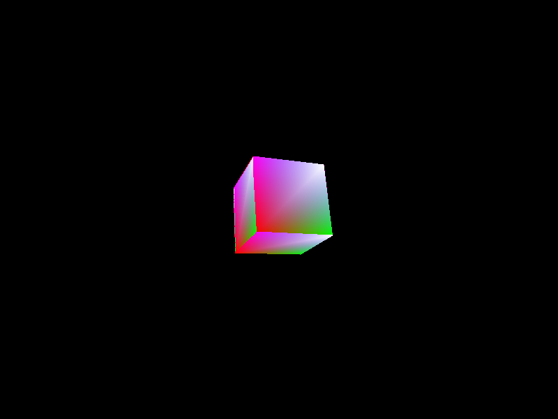
效果如下:

box

可以看出透视关系不正确,这是因为没有做深度测试的原因,因此我们需要实现深度测试。

4 深度测试

我们首先需要在 FrameBuffer 类中加入深度缓冲:

1
2
3
4
5
6
7
8
9
10
11
12
13
14
15
16
17
18
19
20
21
22
23
24
25
26
27
28
29
30
31
32
33
34
35
36
37
38
39
40
41
42
43
44
45
46
47
48
49
50
51
52
53
54
55
56
57
58
59
60
61
62
63
64
65
66
67
68
69
70
/*
* FrameBuffer 类,管理颜色缓冲和深度缓冲
*/
#pragma once
#include "math.h"

class FrameBuffer {
public:
int Width, Height;
std::vector<unsigned char> colorBuffer;
std::vector<float> depthBuffer;

~FrameBuffer() = default;

FrameBuffer(const int& w = 800, const int& h = 600) {
Width = w;
Height = h;
//RGBA四个通道,数组大小为宽*高*4
colorBuffer.resize(w * h * 4, 0);
depthBuffer.resize(w * h, 1.0f);
}

// 重设缓冲区大小
void Resize(const int& w, const int& h) {
Width = w;
Height = h;
colorBuffer.resize(w * h * 4, 0);
depthBuffer.resize(w * h, 1.0f);
}

// 使用给定的颜色清空颜色缓冲,不要使用vector下标访问,会很慢,直接使用指针操作
void ClearColorBuffer(const glm::vec4& color) {
unsigned char* p = colorBuffer.data();
for (int i = 0; i < Width * Height * 4; i += 4) {
*(p + i) = saturate(color.r) * 255;
*(p + i + 1) = saturate(color.g) * 255;
*(p + i + 2) = saturate(color.b) * 255;
*(p + i + 3) = saturate(color.a) * 255;
}
// 同时重置深度缓冲
depthBuffer.assign(Width * Height, 1.0f);
}

// 将颜色写入对应位置
void WritePoint(const int& x, const int& y, const glm::vec4& color) {
if (x < 0 || x >= Width || y < 0 || y >= Height)
return;
int xy = (y * Width + x);
unsigned char* p = colorBuffer.data();
*(p + xy * 4) = saturate(color.r) * 255;
*(p + xy * 4 + 1) = saturate(color.g) * 255;
*(p + xy * 4 + 2) = saturate(color.b) * 255;
*(p + xy * 4 + 3) = saturate(color.a) * 255;
}

// 写入深度,Z-Buffer 中深度范围是 [0,1]
void WriteDepth(const int& x, const int& y, const float& depth) {
if (x < 0 || x >= Width || y < 0 || y >= Height)
return;
float* p = depthBuffer.data();
*(p + y * Width + x) = depth;
}

// 获取深度
float GetDepth(const int& x, const int& y) {
if (x < 0 || x >= Width || y < 0 || y >= Height)
return 1.0;
return *(depthBuffer.data() + y * Width + x);
}
};

正常深度测试应该在片元着色器之后,但是为了避免不必要的计算,可以在扫描线算法中加入深度测试,也相当于实现了 Early-Z 算法:

1
2
3
4
5
6
7
8
9
10
11
12
13
14
15
void ScanLine(const V2F& left, const V2F& right) {
int length = right.windowPos.x - left.windowPos.x;
for (int i = 0; i < length; ++i) {
V2F v = V2F::lerp(left, right, (float)i / length);
v.windowPos.x = left.windowPos.x + i;
v.windowPos.y = left.windowPos.y;

//深度测试
float depth = FrontBuffer->GetDepth(v.windowPos.x, v.windowPos.y);
if (v.windowPos.z <= depth) {
FrontBuffer->WritePoint(v.windowPos.x, v.windowPos.y, shader->FragmentShader(v));
FrontBuffer->WriteDepth(v.windowPos.x, v.windowPos.y, v.windowPos.z);
}
}
}

效果如下:

box

---- 本文结束 知识又增加了亿点点!----

文章版权声明 1、博客名称:LycTechStack
2、博客网址:https://lz328.github.io/LycTechStack.github.io/
3、本博客的文章部分内容可能来源于网络,仅供大家学习与参考,如有侵权,请联系博主进行删除处理。
4、本博客所有文章版权归博主所有,如需转载请标明出处。