1
2
3
4
5
6
7
8
9
10
11
12
13
14
15
16
17
18
19
20
21
22
23
24
25
26
27
28
29
30
31
32
33
34
35
36
37
38
39
40
41
42
43
44
45
46
47
48
49
50
51
52
53
54
55
56
57
58
59
60
61
62
63
64
65
66
67
68
69
70
71
72
73
74
75
76
77
78
79
80
81
82
83
84
85
86
87
88
89
90
91
92
93
94
95
96
97
98
99
100
101
102
103
104
105
106
107
108
109
110
111
112
113
114
115
116
117
118
119
120
121
122
123
124
125
126
127
128
129
130
131
132
133
134
135
136
137
138
139
140
141
142
143
144
145
146
147
148
149
150
151
152
153
154
155
156
157
158
159
160
161
162
163
164
165
166
167
168
169
170
171
172
173
174
175
176
177
178
179
180
181
182
| #pragma once
#ifndef DRAW_H
#define DRAW_H
#include "Global.h"
#include "FrameBuffer.h"
#include "Shader.h"
#include "V2F.h"
class Draw {
private:
int Width;
int Height;
FrameBuffer* FrontBuffer;
Shader* shader;
glm::mat4 ViewPortMatrix;
public:
Draw(const int& w, const int& h) :
Width(w), Height(h), FrontBuffer(nullptr), shader(nullptr) {}
~Draw() {
if (FrontBuffer)
delete FrontBuffer;
if (shader)
delete shader;
FrontBuffer = nullptr;
shader = nullptr;
}
void setModelMatrix(const glm::mat4& model) {
shader->setModelMatrix(model);
}
void setViewMatrix(const glm::mat4& view) {
shader->setViewMatrix(view);
}
void setProjectMatrix(const glm::mat4& project) {
shader->setProjectMatrix(project);
}
void Init() {
if (FrontBuffer)
delete FrontBuffer;
if (shader)
delete shader;
ViewPortMatrix = GetViewPortMatrix(0, 0, Width, Height);
FrontBuffer = new FrameBuffer(Width, Height);
shader = new Shader();
}
void Resize(const int& w, const int& h) {
Width = w;
Height = h;
FrontBuffer->Resize(w, h);
ViewPortMatrix = GetViewPortMatrix(0, 0, w, h);
}
void ClearBuffer(const glm::vec4& color) {
FrontBuffer->ClearColorBuffer(color);
}
void show(std::string& filepath) {
stbi_write_png(filepath.c_str(), Width, Height, 4, FrontBuffer->colorBuffer.data(), 0);
}
void DrawTriangle(const Vertex& v1, const Vertex& v2, const Vertex& v3) {
V2F o1 = shader->VertexShader(v1);
V2F o2 = shader->VertexShader(v2);
V2F o3 = shader->VertexShader(v3);
o1.windowPos = ViewPortMatrix * o1.windowPos;
o2.windowPos = ViewPortMatrix * o2.windowPos;
o3.windowPos = ViewPortMatrix * o3.windowPos;
ScanLineTriangle(o1, o2, o3);
}
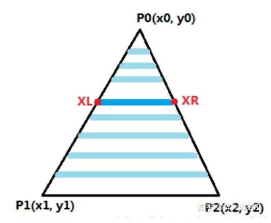
void ScanLine(const V2F& left, const V2F& right) {
int length = right.windowPos.x - left.windowPos.x;
for (int i = 0; i < length; ++i) {
V2F v = V2F::lerp(left, right, (float)i / length);
v.windowPos.x = left.windowPos.x + i;
v.windowPos.y = left.windowPos.y;
FrontBuffer->WritePoint(v.windowPos.x, v.windowPos.y, shader->FragmentShader(v));
}
}
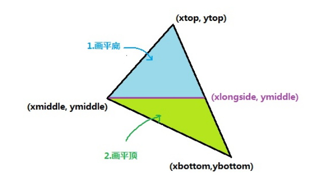
void UpTriangle(const V2F& v1, const V2F& v2, const V2F& v3) {
V2F left, right, top;
left = v1.windowPos.x > v2.windowPos.x ? v2 : v1;
right = v1.windowPos.x > v2.windowPos.x ? v1 : v2;
top = v3;
left.windowPos.x = int(left.windowPos.x);
int dy = top.windowPos.y - left.windowPos.y;
int nowY = top.windowPos.y;
for (int i = dy; i >= 0; --i) {
float weight = 0;
if (dy != 0) {
weight = float(i) / dy;
}
V2F newLeft = V2F::lerp(left, top, weight);
V2F newRight = V2F::lerp(right, top, weight);
newLeft.windowPos.x = int(newLeft.windowPos.x);
newRight.windowPos.x = int(newRight.windowPos.x + 0.5);
newLeft.windowPos.y = newRight.windowPos.y = nowY;
ScanLine(newLeft, newRight);
nowY--;
}
}
void DownTriangle(const V2F& v1, const V2F& v2, const V2F& v3) {
V2F left, right, bottom;
left = v1.windowPos.x > v2.windowPos.x ? v2 : v1;
right = v1.windowPos.x > v2.windowPos.x ? v1 : v2;
bottom = v3;
int dy = left.windowPos.y - bottom.windowPos.y;
int nowY = left.windowPos.y;
for (int i = 0; i < dy; ++i) {
float weight = 0;
if (dy != 0) {
weight = float(i) / dy;
}
V2F newLeft = V2F::lerp(left, bottom, weight);
V2F newRight = V2F::lerp(right, bottom, weight);
newLeft.windowPos.x = int(newLeft.windowPos.x);
newRight.windowPos.x = int(newRight.windowPos.x + 0.5);
newLeft.windowPos.y = newRight.windowPos.y = nowY;
ScanLine(newLeft, newRight);
nowY--;
}
}
void ScanLineTriangle(const V2F& v1, const V2F& v2, const V2F& v3) {
std::vector<V2F> arr = { v1, v2, v3 };
if (arr[0].windowPos.y > arr[1].windowPos.y) {
V2F tmp = arr[0];
arr[0] = arr[1];
arr[1] = tmp;
}
if (arr[1].windowPos.y > arr[2].windowPos.y) {
V2F tmp = arr[1];
arr[1] = arr[2];
arr[2] = tmp;
}
if (arr[0].windowPos.y > arr[1].windowPos.y) {
V2F tmp = arr[0];
arr[0] = arr[1];
arr[1] = tmp;
}
if (equal(arr[1].windowPos.y, arr[2].windowPos.y)) {
DownTriangle(arr[1], arr[2], arr[0]);
}
else if (equal(arr[1].windowPos.y, arr[0].windowPos.y)) {
UpTriangle(arr[1], arr[0], arr[2]);
}
else {
float weight = (arr[2].windowPos.y - arr[1].windowPos.y) / (arr[2].windowPos.y - arr[0].windowPos.y);
V2F newEdge = V2F::lerp(arr[2], arr[0], weight);
UpTriangle(arr[1], newEdge, arr[2]);
DownTriangle(arr[1], newEdge, arr[0]);
}
}
};
#endif
|